|
|


|
Not logged in [Login - Register] |
 |
You Are Not Registered Or Not Logged In |
|  |
|
Corsa Sport » Message Board » Help Zone, Modification and ICE Advice » Wiring/Electrical Genius's please... » Post Reply
|
| pow |
posted on 25th Jun 08 at 14:29 |
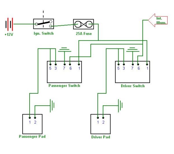
Sorted. I'll draw the full diagram out tonight for ayone to double check as well :) | |
| C2RL R |
posted on 25th Jun 08 at 14:21 |
yeah that'll do it. ignition live connected to the coil of a relay. | |
| pow |
posted on 25th Jun 08 at 14:12 |
Yeah, I can see exactly how the switches work as well. | |
| C2RL R |
posted on 25th Jun 08 at 13:44 |
there is a lamp inside it that comes on when your dash lights do. there is a resistor inside that dims the lights when the heaters are off. when you switch them on you get full voltage to the lights so they come on brighter. | |
| C2RL R |
posted on 25th Jun 08 at 13:40 |
ah shit i've figured it mate. they are switches yes. | |
| pow |
posted on 25th Jun 08 at 11:10 |
They are switches aren't they? | |
| C2RL R |
posted on 25th Jun 08 at 11:00 |
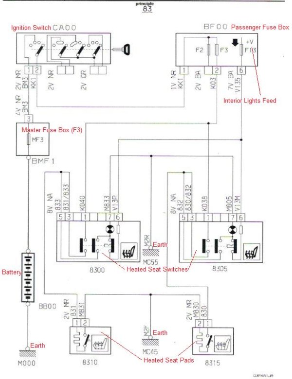
8300 and 8305 are relays are they not??? | |
| pow |
posted on 25th Jun 08 at 07:55 |
Infact, the switch would work with just pins 1 and 3 connected wouldnt it? It wouldnt light up at all though (with the interior lights or when its on). Pin 1 would be the input (IE. from the use box), Pin 3 the output (IE. to the heated seat). | |
| pow |
posted on 25th Jun 08 at 07:42 |
| |
| pow |
posted on 25th Jun 08 at 07:30 |
WTF? Theres no relay in the top picture?!? | |
| luke85 |
posted on 24th Jun 08 at 22:38 |
Without a key that top one is a bit hard to understand but after a quick look late at night it seems you want to take the full load for the seats from the ignition switch and not use any form of relay. | |
| pow |
posted on 24th Jun 08 at 09:11 |
excelenttt :cool: | |
| Fonz |
posted on 24th Jun 08 at 08:31 |
yep its the same but simple version of it :thumbs: | |
| pow |
posted on 24th Jun 08 at 08:14 |
Who knows, but it looks the same doesnt it? | |
| Fonz |
posted on 24th Jun 08 at 08:13 |
ah yes i see it now, looks right cant see why it wouldnt work but only one way to find out! | |
| pow |
posted on 24th Jun 08 at 08:05 |
Dunno, but the diagram at the top (complicated one I was given to use) both pins are connected to the +ve side of the heated pad (thats what the pads are, its for heated seats this one). | |
| Fonz |
posted on 24th Jun 08 at 07:51 |
why have pins 5 & 3 doing the same thing? do you need both? | |
| Fonz |
posted on 24th Jun 08 at 07:50 |
got a key/legnend? | |
| pow |
posted on 24th Jun 08 at 07:14 |
Anybody? | |
| pow |
posted on 23rd Jun 08 at 21:24 |
Check this for me? |