ed
Member
Registered: 10th Sep 03
User status: Offline
|
Been working on this little project for a while now and made a bit of progress tonight. Thought I'd share it on here 
The idea is, you have a lightbox which contains partitions which are individually illuminated by LED arrays on self adhesive PCBs. There is a stencil on the top of lightbox which has words cut out and when the LEDs illuminate correctly the time is told using words. A complicated solution to a simple problem, telling the time. The idea came from Instructables and the board is powered by Arduino which is an open source electronics prototyping platform. Arduino is really useful because you simply code in C and there is lots of info online to get you going.
PCB material was cut to size:

Cut PCB by edcs, on Flickr
PCB negative was printed onto tracing paper and then a lightbox was used to expose the photo resist on the PCB ready for developing:

PCB In Lightbox by edcs, on Flickr
Once the photoresist was developed (no photo), the PCB's were etched in acid:

PCB's Being Etched by edcs, on Flickr
Etched PCB's:

Completed PCB's by edcs, on Flickr
A populated PCB - it took an age to drill all the holes! Soldering wasn't too bad though as I used sockets for all the IC's to protect them from my unskilled hands!

Populated PCB by edcs, on Flickr

PCB Underside by edcs, on Flickr
I used a USB to TTL Serial thingie to program the Arduino - the board was designed so that the processor could be programmed without removing it:

USB to Serial Programmer by edcs, on Flickr
Programming the board:

Programming the Arduino by edcs, on Flickr
Applied power to the board and everything worked! Green LED means power, the red LED flashes during boot up and the flashes every second thereafter - I think I might need to replace the LED resistors as they are a bit bright:

It Works! by edcs, on Flickr
Used a laser cutter to cut out the plastic components of the clock. I designed it in Solidworks and created vector graphics at 1:1 scale to send to the laser:

Laser Cutting the Lightbox by edcs, on Flickr

Laser Cutting Complete by edcs, on Flickr
Did a dry assemble of the lightbox with all the partitions in it. I noticed that I'd messed up the tolerances on the slots that are used to fit the thing together with, so the joints were all a bit loose  : :

Dry Assembly of Lightbox by edcs, on Flickr
I packed the joints out with masking tape and everything fitted together without falling to bits!

Lightbox All Assembled by edcs, on Flickr
Then I had to apply vinyl stencil to the clear acrylic front - never done this before, no idea if I did it right but it all worked with no bubbles, tears or missing bits:

Stencil and Acrylic Front by edcs, on Flickr
I pulled the whole backing off and applied soapy water to it so the stencil could slide about when aligning the acrylic front - apparently this is the noob way:

The Stencil Ready to be Applied to Front by edcs, on Flickr
Seemed to come out nicely:

Masking Tape Removed by edcs, on Flickr
I then applied an opaque filter to the back of the assembled stencil - it's not quite opaque enough for my liking so I need to apply another layer. I used my laptop as a backlight to try and see what it would look like fully assembled:

Diffuser Applied - Using Laptop as a Backlight by edcs, on Flickr
I then fitted the stencil assembly to the lightbox assembly to see what the letters would look like when they wren't illuminated. I want them to be a little bit 'whiter' hence applying another layer of filter to the back of it:

Stencil Fitted to Lightbox by edcs, on Flickr
So, all I have to do now is apply the LED PCB's and wire them up! That's going to be quite tricky as there will be quite a few wires involved with that...

|
Ian
Site Administrator
 Registered: 28th Aug 99
Location: Liverpool
User status: Offline
|

Can't wait to see that working.
|
DannyB
Premium Member
 Registered: 6th Feb 08
User status: Offline
|
Was looking at these yesterday, expensive though 
http://store.biegertfunk.com/us/
|
ed
Member
Registered: 10th Sep 03
User status: Offline
|
Wow - they are expensive! This did cost quite a few quid to make and a lot of time though so it's understandable.
[Edited on 01-12-2011 by ed]
|
DannyB
Premium Member
Registered: 6th Feb 08
User status: Offline
|
Yeah, yours looks great and atleast you can say you made it yourself make more and charge less 
|
John
Member
Registered: 30th Jun 03
User status: Offline
|
I love these, been on hackaday a few times. Don't have the equipment to do it though 
|
Russ
Member
Registered: 14th Mar 04
Location: Armchair
User status: Offline
|
how fucking ridiculous 
i love it  how cool how cool
|
ed
Member
Registered: 10th Sep 03
User status: Offline
|
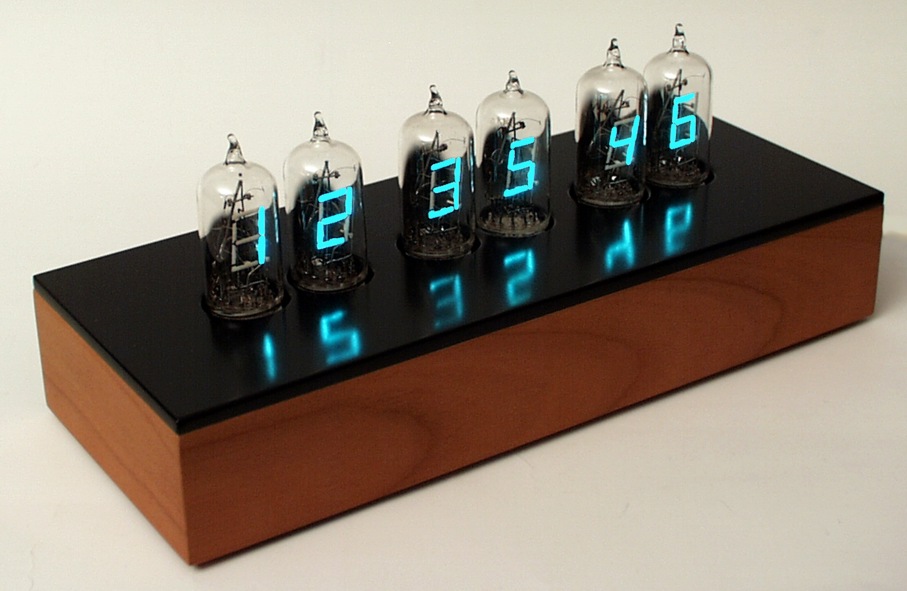
I've also got a load of VDF tubes to build one of these next:
There's something going round my head telling me it's a little bit odd to go to the trouble of making a digital control board to control analogue electronics though 
That and it's probably a bit weird to spend so much time making ridiculous clocks. Hello ladies!
|
DannyB
Premium Member
Registered: 6th Feb 08
User status: Offline
|
You'd be surprised how many people like quirky clocks and how much they would pay for them.
|
John
Member
Registered: 30th Jun 03
User status: Offline
|
I've got an ice tube clock. I love clocks. Want the karlsson word flip clock but need to find a spare £200 for it first.
|
ed
Member
Registered: 10th Sep 03
User status: Offline
|
That Ice Tube clock looks pretty smart Think I might carry on making strange clocks then - I need to try to come up with something original now
|
John
Member
Registered: 30th Jun 03
User status: Offline
|
I've ordered a avr programmer, couldnt get my arduino to work as one for some reason. Then I'll get a gps module, one thing the standard ice tube isn't too good at is keeping time.
|
Brett
Premium Member
 Registered: 16th Dec 02
Location: Manchester
User status: Offline
|
Very cool, nice work
|
Balling
Premium Member
 Registered: 7th Apr 04
Location: Denmark
User status: Offline
|
Nice project and good effort.
One thing I would say though, you should have made the letter spacing more even like on the link Danny posted. Looks much better and less messy.
|
noshua
Member
Registered: 19th Nov 08
User status: Offline
|
|
ed
Member
Registered: 10th Sep 03
User status: Offline
|
Balling: I quite like the non-linear layout of the text, but I'm in partial agreement - rows two and three may be a little bit too tightly packed. I wasn't too keen on sticking random letters in as buffers onto other rows as it would complicate the already tightly packaged lightbox! Just a prototype - might make a much bigger one now as this thing is tiny.
Tested out the LED PCB's - they're very bright. I think I'll modify the code a bit to use PWM to regulate the voltage and reduce the brightness:

Testing LEDs by edcs, on Flickr
Stuck them all down into position:

LEDs Stuck Down Into Position by edcs, on Flickr
Lightbox partitions fitted - my CAD model was correct, everything fitted!

Untitled by edcs, on Flickr
One curious thing is, someone has gone to the trouble of marking the PCB's out with a silk screen to show + and - terminals, however they apear to be inverted. No wonder it was about £18 for several meters of the stuff - they must be rejects. I've just got a whole load of wiring to do now...
|
ed
Member
Registered: 10th Sep 03
User status: Offline
|
Just some screenshots from Solidworks too

Front by edcs, on Flickr

Front - No Cover by edcs, on Flickr
|
John
Member
Registered: 30th Jun 03
User status: Offline
|
I quite fancy a go at this.
Think I could get away all manual?
|
ed
Member
Registered: 10th Sep 03
User status: Offline
|
You should be fine - you might have issues making the PCB if you don't have the right kit but you can buy most of the stuff pre-done.
http://www.instructables.com/id/The-Wordclock-Grew-Up/
http://www.dougswordclock.com/
I've got some spare PCB's too.
|
John
Member
Registered: 30th Jun 03
User status: Offline
|
I've never done PCB etching before but I wouldn't mind having the kit for that anyway.
|
ed
Member
Registered: 10th Sep 03
User status: Offline
|
One thought is, there's nothing stopping you making the lightbox partitions from thick cardboard and sticking it together with masking tape to seal all the gaps. You could then make a wooden surround from MDF which the partitions sit in - that would be much easier to cut as you could use a really sharp Stanley on the cardboard. You could also design it to sit in a photo frame from Ikea - they do some really deep ones which could look good.
You can buy the PCB etching stuff from Maplin, but ideally you'd need a UV lightbox and use photoresist coated stock rather than drawing the PCB out with a pen. You can also use a method called toner transfer to which is a bit more accurate than pen.
[Edited on 02-12-2011 by ed]
|
ed
Member
Registered: 10th Sep 03
User status: Offline
|
Soldered a lot of wires in!

LED's Wired In by edcs, on Flickr

Lots of Wires! by edcs, on Flickr
Tidied it up a bit and connected the socket:

LED Wires Connected to PCB Termainal by edcs, on Flickr
Then powered it up - http://vimeo.com/33164436
|
nathy_87
Member
Registered: 14th Aug 08
Location: West Mids. Drives: koda Fabia VRS 5J
User status: Offline
|
quote:
Originally posted by ed
I've also got a load of VDF tubes to build one of these next:
http://www.tube-tester.com/sites/nixie/different/bl-100/bl-100-48-syl-tu5.jpg
There's something going round my head telling me it's a little bit odd to go to the trouble of making a digital control board to control analogue electronics though
That and it's probably a bit weird to spend so much time making ridiculous clocks. Hello ladies!
I'll have one of them.
|
John
Member
Registered: 30th Jun 03
User status: Offline
|
How much you think this has cost you Ed.
I was looking into it over the weekend, can probably do it for ~£100 with a kit and pre-cut acrylic.
|
ed
Member
Registered: 10th Sep 03
User status: Offline
|
Probably about £90-£100, the vinyl stencils ended up being expensive and the control board isn't cheap either!
|


